Pendulum
For a child, and with a solid assembly, you can develop the idea to, for example, an office souvenir.
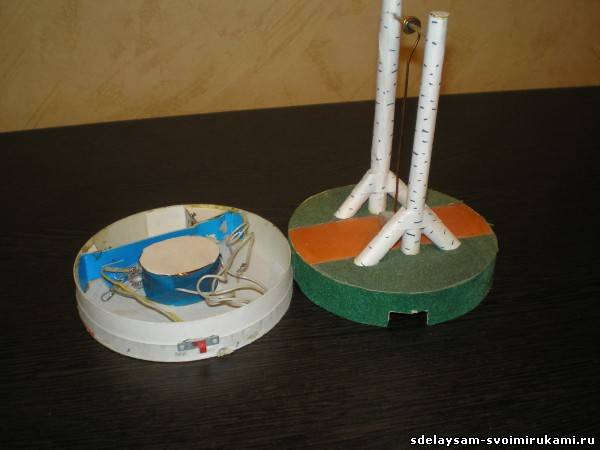
The basis of the toy is the simplest overhanging circuit (although of course it is better to do it on the board), consisting of a transistor, a diode and a specially wound coil hidden in the bottom. The “seat” of the swing is a magnet, it is better to choose a neodymium one, there are a lot of them now, although a regular one will do.
The coil is wound with a double wire with a cross section of approximately 0.25-0.3 each, about 1500 turns, i.e. 2 copper wires are taken in parallel and wound onto a coil. The diagram shows that the end of the first wire is connected to the beginning of the second. I chose the shape of the coil from logical considerations oval, because. a magnet passing over it will interact better along the length of the larger diagonal of the ellipse. I did not use the core, so you can experiment with it. It is better to wind carefully, turn to turn, but not necessarily.
A direct conduction transistor, you can take MP39 ... 42, any diode, a regular 1.5 volt battery. For convenience, it is better to make a switch.
I apologize for the homemade assembly, but I did it in my school days on pure enthusiasm from a diagram from my father's old notebook with diagrams, so I don't really know where it came from, and I just wanted to see how it works as soon as possible.

It starts simply, turn on the device and push the magnet, after a couple of seconds you will notice how intensely the pendulum begins to oscillate. The system will work better if it is possible to create a resonance, i.e. the equality of the frequencies of the circuit and the natural frequency of the pendulum, which is calculated by the formula. Here it is achieved by adjusting all parameters of the pendulum. It is better to fix the connecting rod on 2 bearings, and not on the 1st like mine.